1-Pag-install ng cold storage at air cooler
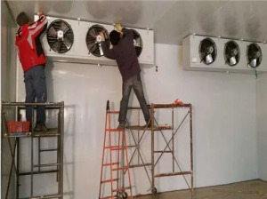
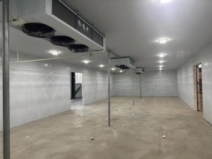
1. Kapag pumipili ng lokasyon ng punto ng pag-aangat, isaalang-alang muna ang lokasyon na may pinakamahusay na sirkulasyon ng hangin, at pagkatapos ay isaalang-alang ang direksyon ng istruktura ng malamig na imbakan.
2. Ang agwat sa pagitan ng air cooler at ng storage board ay dapat na mas malaki kaysa sa kapal ng air cooler.
3. Dapat na higpitan ang lahat ng suspension bolts ng air cooler, at dapat gamitin ang sealant para i-seal ang mga butas ng bolts at suspension bolts upang maiwasan ang malamig na tulay at air leakage.
4. Kapag ang ceiling fan ay masyadong mabigat, ang No.4 o No.5 na anggulong bakal ay dapat gamitin bilang beam, at ang lintel ay dapat sumasaklaw sa isa pang bubong at wall plate upang mabawasan ang karga.
2-ang pagpupulong at pag-install ng yunit ng pagpapalamig
1. Ang parehong semi-hermetic at fully hermetic compressors ay dapat na nilagyan ng oil separator, at isang naaangkop na dami ng langis ay dapat idagdag sa langis. Kapag ang temperatura ng pagsingaw ay mas mababa kaysa sa minus 15 degrees, dapat na mai-install ang isang gas-liquid separator at isang angkop na
Sukatin ang langis ng pagpapalamig.
2. Ang base ng compressor ay dapat na naka-install na may shock-absorbing rubber seat.
3. Ang pag-install ng yunit ay dapat mag-iwan ng silid para sa pagpapanatili, na kung saan ay maginhawa para sa pagmamasid sa pagsasaayos ng mga instrumento at mga balbula.
4. Dapat na naka-install ang high pressure gauge sa tee ng liquid storage filling valve.
3. Teknolohiya sa pag-install ng pipeline ng pagpapalamig:
1. Ang diameter ng copper pipe ay dapat piliin sa mahigpit na alinsunod sa suction at exhaust valve interface ng compressor. Kapag ang paghihiwalay sa pagitan ng condenser at ang compressor ay lumampas sa 3 metro, dapat na tumaas ang diameter ng pipe.
2. Panatilihin ang distansya sa pagitan ng air suction surface ng condenser at ng dingding na higit sa 400mm, at panatilihing higit sa 3 metro ang distansya sa pagitan ng air outlet at ng obstacle.
3. Ang diameter ng mga inlet at outlet pipe ng liquid storage tank ay dapat na nakabatay sa diameters ng exhaust at liquid outlet pipe na minarkahan sa unit sample.
4. Ang suction pipeline ng compressor at ang return pipeline ng cooling fan ay hindi dapat mas maliit sa sukat na ipinahiwatig sa sample upang mabawasan ang panloob na resistensya ng evaporation pipeline.
5. Ang bawat tubo ng likidong labasan ay dapat ilagari sa isang 45-degree na tapyas, at ipasok sa ilalim ng tubo ng likidong pumapasok upang maipasok ang isang-kapat ng diameter ng tubo ng istasyon ng pagsasaayos.
6. Ang tambutso at return air pipe ay dapat magkaroon ng isang tiyak na slope. Kapag ang posisyon ng condenser ay mas mataas kaysa sa compressor, ang exhaust pipe ay dapat dumausdos sa condenser at ang isang likidong singsing ay dapat na naka-install sa exhaust port ng compressor upang maiwasan ang shutdown
Matapos lumamig at matunaw ang gas, dumadaloy ito pabalik sa high-pressure exhaust port, at ang likido ay na-compress kapag ang makina ay na-restart.
7. Dapat na naka-install ang hugis-U na liko sa labasan ng return air pipe ng cooling fan. Ang return air pipeline ay dapat dumausdos patungo sa direksyon ng compressor upang matiyak ang makinis na pagbabalik ng langis.
8. Ang balbula ng pagpapalawak ay dapat na mai-install nang mas malapit hangga't maaari sa palamigan ng hangin, ang solenoid valve ay dapat na naka-install nang pahalang, ang katawan ng balbula ay dapat na patayo at bigyang-pansin ang direksyon ng likidong labasan.
9. Kung kinakailangan, mag-install ng filter sa return air line ng compressor upang maiwasan ang pagpasok ng dumi sa system sa compressor at alisin ang moisture sa system.
10. Bago i-fasten ang lahat ng sodium at lock nuts sa refrigeration system, punasan ang mga ito ng refrigerated oil para sa lubrication para mapahusay ang performance ng sealing, punasan ang mga ito pagkatapos i-fasten, at i-lock nang mahigpit ang packing ng bawat section door.
11. Ang temperature-sensing package ng expansion valve ay nakakabit sa 100mm-200mm mula sa outlet ng evaporator na may mga metal clip, at mahigpit na nakabalot ng double-layer insulation.
12. Matapos makumpleto ang hinang ng buong sistema, ang pagsubok sa higpit ng hangin ay isasagawa, at ang dulo ng mataas na presyon ay dapat punan ng 1.8MP nitrogen. Ang low pressure side ay puno ng nitrogen 1.2MP. Gumamit ng tubig na may sabon upang suriin kung may mga tagas sa panahon ng pressure, maingat na Suriin ang mga welding joints, flanges at valves, at panatilihin ang presyon sa loob ng 24 na oras pagkatapos ng simpleng pagkumpleto nang hindi bumababa ang presyon.
Oras ng post: Mar-30-2023


